Creating a hooklift truck model can be an invaluable endeavor for business owners interested in innovative logistics solutions. This guide provides a detailed roadmap, from defining project goals and designing key systems to constructing a robust chassis and refining safety protocols. Each chapter strategically outlines the essentials for successfully building a functional hooklift truck model, enabling you to understand its mechanics and practical applications. Whether you aim to showcase your craftsmanship or replicate the functional aspects in your fleet, this DIY project is a blend of creativity and technical skill essential for any forward-thinking entrepreneur.
把愿景变成尺寸:为你的惊艳钩臂卡车确定目标与规模
目标与规模:把愿景变成可实现的制作计划
开始制作钩臂卡车之前,最关键的抉择不是选材料或驱动方式,而是明确你的目标和规模。这个决定像一把分水岭之刀。它影响预算、工具、所需技能、安全边界与最终的可玩性。按用途倒推设计,会比盲目模仿任何现成方案更节省时间和资源。接下来我将通过一条连贯的思路,帮助你把大致想法变成清晰的制作蓝图。
首先定义目标:你要的是外观优秀的展示模型,还是能实际工作的功能性原型?展示模型允许牺牲部分功能而追求细节,例如精确的车身线条和逼真的油漆。功能性原型则要求结构强度与活动部件可靠,并可能需要动力源、控制系统与负载测试。如果你是把项目当成学习练习,目标可以更务实:着重掌握某一项技能,如金属加工、电子控制或液压模拟。
明确目标后,考虑受众与使用频率。放在家中或课室展示,耐用性可以适中;用于教学演示或户外互动,则需更高的耐久性与安全系数。若计划给儿童操作,设计必须纳入速度限制、夹持强度保护与防夹结构。目标的选择直接决定你是否需要加装遥控、限位开关或力矩保护装置。
接着选择规模。常见选择从微缩桌面模型到可载荷的大型原型都有其合理性。微缩模型适合快速实现并呈现复杂细节。中等比例给你实现简单活动机构的空间,同时不会要求大型加工设备。大型实体模型则需要金属加工、真实液压或强力电机,并伴随更高的成本与更严的安全要求。衡量时把三项放在天平上:可用空间、预算和可获得的技能或协助资源。
从材料和工具角度考虑规模带来的差异。小比例作品可以用塑料板、3D 打印件、细金属丝和微型舵机来复刻动作。中等比例常见材料包括软木、轻型铝型材、小型电机和标准舵机,工具可为家用电钻、锯和焊接枪。大型模型通常需要钢材、标准液压缸、电动马达或气动组件,并可能需要数控切割或专业焊接服务。将材料清单与可用工具匹配,是避免项目半途搁置的关键。
时间和成本规划也受规模影响。微缩模型几天到几周可完成,成本通常在几十到几百美元不等。中等规模项目可能需要数周到数月,并涉及较多配件与控制元件,成本上升明显。大型实体模型的时间表和预算会呈阶梯式上升,同时需要按阶段进行强度和安全测试。把工作分解成里程碑:草图、底盘、钩臂机构、动力与控制、外观处理,每个里程碑设定时间和材料预算,能让项目进展可控。
技术复杂性是另一个考量点。小型项目可以用手动杠杆或绞盘+滑轮实现钩臂动作。中等项目可选择舵机、微型气缸或电动绞盘来模拟液压动作。大型作品如果要接近真实工作流程,需要使用液压缸与泵,或质量可靠的电动缸,同时配备阀门和安全锁紧机构。你的决定应根据对电子、液压或机械知识的掌握程度来做出。如果你希望一步到位实现自动控制,可以在中等规模上练习微控制器与传感器,再把经验迁移到更大项目。
安全与测试不能在任何规模上被忽视。即便是桌面模型,也要避免尖锐边缘和易脱落的小件。大型或带电动驱动的模型需要强制的限位开关、应急断电与负载测试流程。逐步测试始终是最稳妥的方法:先单独测试驱动单元,再在轻载下测试整体联动,最后逐步增加负荷并长时间运行检测热量、松动与疲劳痕迹。
对初学者的实际建议是:从能带来成就感的最小可行产品开始。确定你想要展示的最关键动作,例如“钩臂能伸出并挂起容器”。围绕这个动作选规模和材料。比如要实现可遥控的钩臂动作,中等比例、轻型铝型材加上小型电机与绞盘通常是表现最佳的组合。你会在这个过程中学习传动比计算、舵机校准与简易控制接口的搭建。
如果你的目标偏向教学或互动展览,考虑模块化设计,把钩臂系统做成可拆卸模块。这样你可以分别优化传动、控制与外观。模块化还能降低运输和维护成本。对于需要频繁展示的作品,选取耐用的五金件和标准化紧固件非常重要。标准件便于后期更换和升级。
最后,从创意角度审视规模选择。让作品“惊人”的不是单纯放大尺寸,而是恰如其分地表现核心功能,并通过细节强化真实感。微缩作品可在涂装和细微机械结构上取胜。中等作品能在互动与稳定性上打动观众。大型作品如果能安全地模拟真实工作流程,就会在视觉和体验上带来强烈冲击。
如果你需要查阅真实车辆的结构细节,以便在模型中还原关键工艺步骤,请参考一份有关真实车辆结构的详尽资料,这会对你的高精度设计产生帮助。也可以阅读关于工装配件与升降平台的实用入门文章,了解常用的安装与安全做法,例如 liftgates for trucks。
更多技术蓝图与结构图可作为后续设计的参考,例如一份详尽的车辆结构解读资源:https://www.fotontruck.com.cn/product/1324.html
通过把目标和规模清晰化,你的制作计划会更具针对性。下一步是把这个决定映射到草图与零件清单中。那一步将把抽象的愿景,转化为可执行的工作包。
Optimizing a Hooklift System for DIY: Practical Design and Safety Principles
Optimizing a Hooklift System for DIY: Practical Design and Safety Principles
Designing a hooklift system that performs smoothly and looks convincing takes more than copying a picture. Optimization combines physics, thoughtful materials, and careful testing. This chapter walks you through practical choices for a scaled DIY hooklift, explains the key mechanical trade-offs, and gives clear steps to make a reliable, repeatable system for models or small prototypes.
Start with a clear scope. Decide if your build is a static display, a functional model for light loads, or a teleoperated demonstrator. That choice drives size, material, and power decisions. For educational or hobby projects, a scale between 1:18 and 1:24 balances manageability and visible mechanics. Larger, heavy-duty builds need professional design and certification; this guide focuses on safe hobby-level implementations.
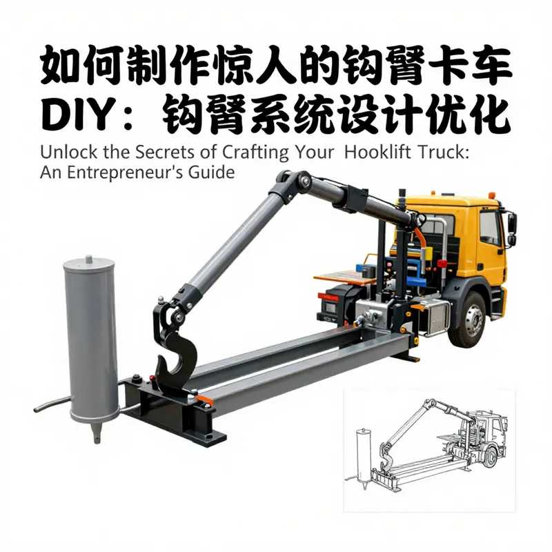
The central idea of a hooklift is mechanical advantage. A long arm and clever linkage let a small actuator lift a bulky container. Optimize leverage by studying arm length, pivot placement, and attachment geometry. Place the main pivot low on the chassis to reduce vertical travel, and position the hook on a short sub-arm to shorten the final pull distance. This improves predictability and reduces peak loads on the actuator.
Material choice should follow load demands. For models, plywood, aluminum sheet, or 3D-printed composite parts provide a good strength-to-weight ratio. Use steel for any critical pins or loads bearing elements. Avoid brittle plastics at pivot points. When welding or bolting metal parts, ensure alignment with fixtures or jigs to prevent bind during motion.
The actuator is a major design decision. Three practical options work well for hobby builds:
- Simulated hydraulics: Small pneumatic cylinders or micro-hydraulic actuators mimic real motion. They give smooth travel and are compact. Use fittings rated above expected pressure. Include a simple relief valve to prevent overpressure.
- Electric winch and pulleys: A geared DC motor driving a winch can pull the hook arm. Use a block-and-tackle or a pulley cascade to increase mechanical advantage. This approach is easy to control with PWM motor drivers and works well when space for a linear actuator is limited.
- Manual lever linkage: For simplicity, a hand-operated lever with a spring return can demonstrate concepts without motors. This is ideal for classroom demos where safety matters most.
Optimizing the linkage yields smoother motion and reduces actuator size. Two common families work well for DIY:
- Multi-link (four-bar) arrangements produce near-linear motion at the hook tip. They distribute loads across members and reduce peak bending moments. This requires precise pin spacing and matched lengths for symmetry.
- Telescopic or sliding multi-stage arms extend range without huge pivots. Use low-friction liners and captive retaining rings to prevent accidental separation.
Calculate expected forces early. For a realistic model, estimate container weight and the worst-case angle. Convert this to torque at the main pivot. Use a safety factor of at least three for hobby builds. This prevents component fatigue and improves longevity. Simple spreadsheets help: input weight, arm lengths, and pivot offsets to get peak bending and pivot shear.
Bearing selection matters. Use sealed bearings for rotating pins and roller assemblies. Ball bearings on rollers reduce friction during box insertion and removal. For slides, choose bronze or polymer bushes when noise and simplicity matter. Lubrication points should be accessible; design small grease nipples or removable covers.
A reliable locking strategy is non-negotiable. Even models benefit from a two-stage lock. Combine a powered or spring-actuated lock with a mechanical catch. For example, a solenoid or small servo can position a retaining pin while a secondary mechanical latch auto-engages as the container seats. This prevents accidental release if power fails.
The interface between chassis and body requires solid thinking. Build a rear mount plate that spreads load into the chassis rails. If you repurpose an RC car frame, reinforce the area around the main pivot with a crossmember. Welding plates or bolting gussets are both effective. Ensure the center of gravity of the mounted container remains within safe bounds for the chassis.
Reduce friction where the container slides on the subframe. Use hardened steel rollers or low-friction polymer pads. Angle the guide rails slightly to self-center the box during retrieval. Test and tune roller spacing so the box doesn’t jam when partially engaged.
Control strategy affects perceived smoothness. For electric systems, soft-start motor controllers and ramping algorithms reduce shock loads. If using a linear actuator, add limit switches to prevent overtravel. For pneumatic systems, a two-stage valve can slow motion near end positions. An Arduino or similar microcontroller provides simple, safe control logic for demos. Add a dead-man switch for manual operation tests.
Sensors add polish and safety. A simple ultrasonic sensor detects approach distance. Reed switches or magnetic sensors confirm fully seated positions. Visual indicators, like LEDs, give instant status feedback. Wiring should be routed away from moving joints and protected with braided sleeving. Fuse motor circuits and clearly label power sources.
Testing and iteration are where design optimization pays off. Begin with bench tests under no load. Verify smooth motion, absence of binding, and proper alignment. Progressively add weight in measured increments. Record actuator current, deformation at key points, and roller behavior. If a component shows excessive deflection, redesign with a thicker section or additional support. Keep test runs short to avoid overheating motors.
Maintenance considerations extend service life. Design for easy component replacement. Use threaded inserts for repeated disassembly. Protect exposed metal with paint or powder coating to avoid corrosion. Keep hydraulic or pneumatic lines tidy and well-clamped to avoid chafing.
Aesthetics and realism are often overlooked but important. Scale appropriate fasteners, painted textures, and visible hydraulic lines or cable routing sell authenticity. Add simple details like hinge caps, simulated grease fittings, and realistic container ears. These small touches make a DIY hooklift feel professional.
Above all, respect legal and safety boundaries. A hobby build is for display or light demonstration. Do not attempt to replicate a full-scale street-legal vehicle without professional engineering and certification. When in doubt, restrict the model to contained environments and supervised demonstrations.
For practical inspiration on mounting and guide systems, review a detailed lift-gator resource that covers frame and roller design: lift-gator reference.
Relevant examples of small-scale assembly techniques and motion demonstrations can clarify complex steps. Refer to a visual tutorial for assembly sequencing and actuator placement: https://www.pinterest.com/pin/123456789012345678/.
With these principles, you can optimize a DIY hooklift system that is safe, convincing, and enjoyable to operate. Focus on predictable mechanics, robust joints, and layered safety. Iterate from prototypes to refinements and document each change. That disciplined approach yields a hooklift model that reliably expresses the full idea behind the real machines, while staying within the safe limits of a hobby project.
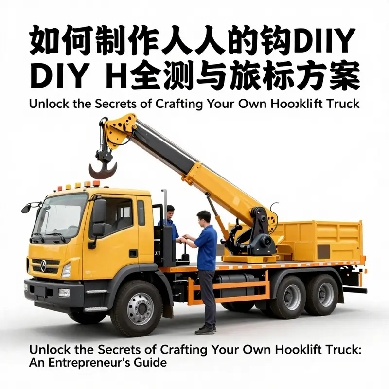
How to Build an Amazing Hooklift Truck DIY: Mastering the Chassis and Frame Foundations
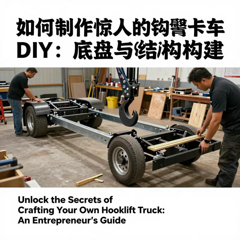
The backbone of any memorable hooklift truck DIY project is not the moving arm or the clever grabbing mechanism alone, but the chassis and frame that carry every dynamic load, every trial lift, and every moment of testing. For hobbyists aiming to showcase a convincing principle or to educate others through a tangible model, the chassis must be rigid, predictable, and forgiving of imperfect fabrication. The goal is not to imitate a full commercial machine at full scale, but to demonstrate the essential balance between strength, weight, and maneuverability. A well-chosen base allows the hook system to work as a true unit rather than a clumsy add-on. In practice this means starting with a stable, scalable platform, and then layering in the structural refinements that light up the concept: how the container cradle interacts with the frame, how the pivot points resist bending moments, and how the return paths for forces travel along the chassis without causing deformation or misalignment over repeated cycles. The beauty of a DIY approach lies in its modularity, so the starting point should be a chassis that can accept a detachable or semi detachable subframe, a philosophy that keeps the project approachable while remaining faithful to the physics of lifting and balancing weight. The educational value emerges when the model behaves similarly to a full-size system in a scaled sense: the lift sequence, the alignment of the hook, and the stability of the vehicle during operation all hinge on a frame that is more than a decorative shell. To this end, the first major decision concerns the drive and the fundamental geometry of the base. A six-by-four drive arrangement is widely referenced in heavy hauling concepts for its traction and stability under load. The exact configuration can be adapted to a scale model, but the underlying principle remains the same: the chassis must provide a wide, grounded footprint and a robust center of gravity that keeps the lifting axis close to the vehicle’s line of travel. In a classroom or workshop setting, you might lean toward a simplified, decoupled base that uses readily available materials yet preserves the essential stiffness. The wheelbase, whether you target a 4500 to 4700 millimeter range or a scaled equivalent, should be chosen not as a cosmetic feature but as a deliberate design parameter. A longer wheelbase improves straight-line stability when the hook is extended and the container is at height, while a shorter one enhances turning agility in confined spaces. The steel frame itself, even in a model, should evoke the same logic as its real-world counterpart: a ladder or truss-type backbone with cross members that resist torsion and bending. High-strength alloys or combinations of steel and aluminum can achieve a balance between weight and rigidity; the trick is to keep the frame continuous where it counts, especially around the areas where the hook arm mounts and where the container base travels in its guidance track. When developing your plan, imagine the frame as a sequence of concentric safety nets: the outer shell must not bend; the inner lattice must not ripple under load; and the joints must not loosen after a handful of cycles. This is where the relationship between the base and the lifting mechanism becomes critical. The frame should guide the hook’s rotation smoothly, with sufficient clearance to prevent binding at full extension or if minor misalignments occur during fabrication. For a model that remains faithful to the principle, the design should allow for adjustable mounting points that accommodate tiny tweaks in geometry after initial assembly. A practical approach is to create a detachable subframe or mounting plate at the rear of the chassis. This plate can house the pivot hardware and the lower bearing surfaces that the hook arm relies on. By using modular fasteners and slotted holes, you gain the ability to tune the system without cutting new steel each time. The goal is not perfection at first cut but iterative refinement through testing. The structure should also acknowledge the way forces travel along the frame when the arm lifts a container. The moment generated at the pivot is transmitted through the chassis as a combination of bending and shear. If the rear section carries the weight, the frame must be proportioned to handle that moment without sagging. Even in a scaled project, a careful balance of mass distribution helps prevent dynamic instabilities that might surprise the operator during a demonstration or school presentation. At the same time, the aesthetics of the frame contribute to the learning experience. A clean, well-braced undercarriage with neatly arranged tubing or extrusions communicates the discipline behind real-world heavy equipment. It invites curious eyes to follow the path of force from the container cradle through the mount, into the chassis, and down to the road. The visual clarity reinforces the engineering logic: you can see how the hook arm’s extension path aligns with the vehicle’s longitudinal axis, how the rotation is anchored by a solid pivot, and how the supporting rails keep the container aligned as it rises and lowers. As with any mechanical build, safety starts at the design phase. Even when working with scaled materials such as PVC, light aluminum, or hollow steel sections, the same checks apply. Eliminate sharp edges, ensure fasteners are recessed or shielded, and plan for secure locking mechanisms that hold critical moving parts in place during demonstration. In the broader scope of the project, the chassis can be viewed as the canvas that supports the art of lifting, while the hook arm and container cradle constitute the moving sculpture. The integration of a sliding or rolling platform beneath the container area can drastically reduce friction and make the operation feel more natural. Consider a low-profile inclined platform with a gentle ramp, equipped with rollers or low-friction sliders that tolerate repeated cycles. This approach minimizes resistance during loading and unloading, a small but meaningful factor in creating a model that operates with grace rather than roughness. When you assemble the rear structure, it helps to contemplate a future upgrade path: a detachable container cradle that can be swapped for different bin sizes, or a modular hook arm that can be adjusted for various scale models. A design that anticipates future modifications saves time, reduces waste, and teaches the valuable engineering habit of planning ahead. For builders seeking a more hands-on path to real-world insight, the chassis and frame work often converges with teachings from resources focused on lift systems and vehicle integration. A practical takeaway is to maintain alignment between the pivot axis and the container’s center of gravity. Misalignment makes even a sturdy frame feel brittle and introduces wobble during lift. Regular checkups and incremental testing, beginning with harmless loads and progressing to heavier demonstrations, ensure the system remains in harmony as you refine tolerances. The discipline of testing also prompts a deeper appreciation for the interplay between weight, balance, and motion. As you move through these stages, remember that the model’s value lies not in mimicking every commercial detail but in demonstrating the core physics: how a solid, well-braced chassis enables the hook mechanism to operate with precision, how the cradle and rails support smooth engagement, and how a thoughtful layout reduces wear over time. The chapter on chassis and frame foundations can grow more powerful when connected to broader kitchen-table engineering practices, from modular subframes to adjustable pivots, and from low-friction guides to robust locking strategies that keep the system safe for demonstrations and educational purposes. In this spirit, a modular, well-reinforced base becomes more than a starting point; it becomes the quiet engine of the project, inviting experimentation with different container sizes, different lift sequences, and different ways to present the principle of a hooklift in action. For readers curious about how these ideas translate into more advanced designs, our broader guide on lift systems offers a complementary perspective and practical pathways to integrate these concepts with other lifting technologies. See our lift gates guide for a deeper dive into how a modular plate and rolling interface can be scaled up to handle larger payloads while preserving control and safety. External resources and explanations from industry references emphasize the same core truths: strong foundations enable dynamic systems to perform reliably under load, while careful alignment prevents the kind of fatigue that undermines performance over time. As you port these principles into your workshop, keep the emphasis on clarity of motion, predictable responses, and reproducible results. The chassis and frame may be the quiet backbone of the project, but they are also the stage on which the entire educational performance unfolds. By building a rigid, thoughtfully braced, and modular base, you give your hooklift concept a sturdy reality—one that demonstrates clearly how a container cradle can be integrated with a vehicle frame, how rotation can occur without torsion, and how testing can reveal the subtle balances that turn a prop into a convincing working model. In practice, this is how you transform a collection of materials into a coherent, demonstrable system that embodies the core lessons of hooklift technology while remaining accessible for education, display, and hobbyist exploration. External reference: https://www.foton.com.cn/products/ldc/
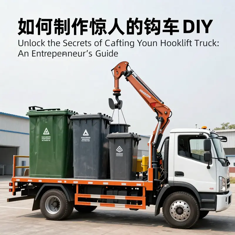
如何制作惊人的钩臂卡车DIY:垃圾桶模块设计和使用
如何制作惊人的钩臂卡车DIY:垃圾桶模块设计和使用
From the outset, the challenge and the thrill lie in translating a heavy, real-world mechanism into a safe, educational, and visually compelling DIY project. The centerpiece of that translation is not the chassis alone but a detachable garbage-bin module that can be mounted, unmolded, and reused with minimal fuss. This approach mirrors the core advantage of real hooklift vehicles: modularity. A well-designed module makes the system practical for demonstrations, school projects, or hobby exhibitions while avoiding the risks and costs associated with full-scale, on-road machinery. The aim is to demonstrate the fundamental principle—grab, lift, tilt, and release—without inviting danger or legal complications. The chapter that follows threads these ideas together into a cohesive blueprint built from low-cost materials, simple power sources, and clear mechanical logic.
The first principle is modularity. Treat the garbage-bin module as a stand-alone payload unit that can be swapped in and out of a purpose-built chassis. This separation clarifies design priorities: the base chassis must be robust enough to support repeated lifting cycles, while the bin module must provide reliable attachment points and predictable geometry. Instead of trying to replicate every detail of a full-scale system, aim for a faithful mimicry of key motions: the arm extends, the hook engages, the container rises to a stable height, and the container tilts or dumps when needed. The interface between module and chassis becomes the real heartbeat of the project. A simple, well-defined interface reduces the risk of misalignment during mounting and demounting and lets you prototype quickly with interchangeable payloads.
With the modular concept established, the practical design begins with a reasonable base platform. For hobbyists, a light, sturdy frame made from square tubing or aluminum profiles provides a reliable skeleton. The front wheels must turn smoothly for steering during demonstrations, while the rear section carries the load of the bin and the lift apparatus. The tail-end positioning of the hook is deliberate: mounting the hook at the rear lowers the center of gravity during lifting and keeps the payload aligned with the vehicle’s longitudinal axis. This alignment is crucial for a stable simulated operation and reduces sway when the bucket module engages the lift.
The heart of the system is the lifting mechanism itself. A realistic hooklift action can be suggested by a parallelogram linkage, which preserves the bin’s orientation as it rises. This arrangement is known for keeping the load level, even as the arm extends or retracts. In a low-budget project, you can simulate the hydraulic action with a single-acting cylinder or a compact electric actuator connected through a simple linkage to the arm. If you choose a hydraulic vibe, a small, off-the-shelf single-acting hydraulic cylinder paired with a hand pump can suffice for demonstration purposes. The advantage of hydraulic-like behavior is smooth, progressive motion and the natural damping that helps to avoid abrupt movements during testing. If you opt for an electric system, use a reversible motor or a geared DC motor with a limit switch arrangement to define “up” and “down” positions. The key is predictable control and quiet operation that tells a coherent story of the lifting cycle without mechanical jamming.
Designing the garbage-bin module itself is a careful balance of durability, modularity, and aesthetics. The container should be a self-contained shell with a robust back interface—two symmetric吊耳 or lifting lugs, and a recess or slot that matches the hooks on the lifting arm. Materials should resist corrosion and rough handling; thin-walled metal or reinforced plastic can work well for a demonstrator. The volume of the bin should be scaled to the chassis so that the weight distribution remains manageable during lift cycles. A practical path is to fabricate the bin from a sheet metal shell or a pair of laminated panels with a stiff interior frame, then cap it with a weatherized outer skin for visual impact. The bottom of the bin can include a small drain or weep hole to prevent standing liquid in demonstrations where moisture is present.
To ensure quick swap-out capability, attach the bin module to a standardized mounting plate on the chassis. The plate should incorporate two or more fixed guide pins that align with corresponding holes on the bin’s back wall. A locking mechanism—either a simple cam latch or a spring-loaded catch—secures the module during a demonstration. The interface should be rugged enough to withstand repeated engagement and disengagement, yet easy enough for a student or hobbyist to operate without specialized tools. With the module in place, the hook apparatus can engage two symmetric吊耳, which in turn feed into the clamp or grab mechanism on the arm. This simple, mirrored design reduces asymmetry, minimizes binding, and helps maintain a clean, repeatable motion path during lift cycles.
Control systems for this setup can be intentionally modest and educational. A small control box inside the work area allows the operator to simulate “extend” and “retract” actions with tactile buttons. For a more ambitious project, a microcontroller-based remote control can coordinate the lift with a light sensor or a timer to illustrate sequencing—the hook closes, the arm rises, the container reaches the target height, and the bin tilts to demonstrate discharge. Whether you use a manual system or a remote, safety interlocks are essential. A simple interlock could be a manual brake that must be engaged before the lift can start, or a physical guard that prevents accidental operation when the bin is not properly seated.
The visual language of the project matters as well. The finished model should convey the impression of genuine industrial equipment without implying readiness for actual service. A tidy chassis, clean weld lines, and a consistent color or skin treatment help communicate the engineering intent. The bin module should look like a real payload unit, with reinforced corners, mounting tabs, and paint that resists chips. A clean, legible label system—color-coded latches, a small schematic etched on a plate showing the lifting sequence—adds to the educational value. For a further layer of realism, you can add a lightweight exterior shell that mimics the silhouette of a municipal bin, but ensure the shell remains light enough to avoid misrepresenting the model as a working vehicle.
From an instructional perspective, the project gains depth by tying the practical work to a few core physics ideas. The lift is not merely about height but about maintaining the payload attitude and the center of gravity. As the bin rises, the linkage geometry should minimize tilting. If you notice significant tilt or sway, adjust the linkage angles or tighten the joints. The system’s motion is a careful dance between leverage, inertia, and ballast. Testing under controlled, low-load conditions helps you observe these dynamics safely and iteratively improve the design. A methodical approach—build a scale model first, validate the motion, then gradually introduce larger loads—protects both the builder and the object being demonstrated.
A small but important detail is the interface reference to real-world practice. In many professional contexts, the payload container is designed with a standard back that accepts the lifting mechanism with minimal alignment effort. Your DIY project can reflect this by incorporating a back plate with precise holes for quick insertion and removal of the bin module. The idea is to give observers the sense that they are watching a genuine, repeatable exchange: a specific hook engages, a latch clicks into place, and the bin settles onto the arm. For readers who want a practical path toward real-world interfaces without overcomplicating the build, consult the truck box guide, which demonstrates how to design an effective, standardized truck-box interface in a hands-on, approachable way. truck box guide.
Beyond the core mechanics, there is room for creative extension that preserves safety and clarity while expanding the educational value. A transformable model—one that can switch between a straight lift and a tilt-dump mode—offers a vivid demonstration of how different end-effectors or workflows demand different kinematic strategies. Integrating basic sensors, such as a simple proximity sensor to indicate when the bin is fully seated or a light that signals the end of a lift cycle, can elevate the learning experience without complicating the core design. If you want to push further, you can add a basic audio cue or LED indicators to simulate “dump complete” signals, reinforcing the cause-and-effect relationship between control actions and mechanical responses. The overall objective remains clear: the demonstration should illuminate the relationship between actuator action, linkage geometry, and payload behavior while staying within the safe, educational boundary that makes it suitable for classrooms or hobby workshops.
The path from concept to a tangible model is not merely about assembling parts; it is a disciplined exercise in translating a professional system into teachable mechanics. The garbage-bin module is more than a container. It is a portable payload that, by virtue of its detachable design, unlocks a family of demonstrations. When you look at the completed model, you should be able to explain why the parallelogram linkage preserves orientation, how a single-acting cylinder can mimic hydraulic action, and why interface standards matter for quick reconfiguration. You should also be able to describe the safety measures that prevent misconceived attempts at real-world operation in a school or maker space. That clarity—engineered simplicity paired with a convincing physical presence—is what makes this project “amazing” in a way that resonates with both craft and science.
For readers seeking a deeper dive into the mechanics of the real systems that inspired this project, a concise treatment of the assembly and linkage behavior can be found in the truck box guide linked earlier. The page offers practical sketches and methods for aligning the bin with the lift mechanism without overreaching the DIY scope. It is not a substitute for hands-on experimentation, but it provides a stable reference frame that helps keep your build grounded in realistic design principles. The emphasis remains on safety, modularity, and educational value rather than on recreating a full-scale, roadworthy machine. The ultimate payoff is a model that earns attention for its craftsmanship and teaches the underlying physics of lifting, grabbing, and releasing a payload with clear, observable cause and effect.
External resource reference: How a Hydraulic Wastepaper Bin Lift Works – Explained in Detail. https://www.youtube.com/watch?v=ZqR9e6xkXoQ
Controlled Power: Safe Testing and Practical Implementation for a DIY Hooklift Truck Prototype
Designing safety into every step is the difference between a neat model and a reliable demonstration prototype. A functional hooklift truck DIY should behave predictably under load, respond instantly to faults, and protect operators and bystanders. This chapter outlines a coherent implementation plan that blends practical build steps with robust safety testing. It avoids heavy industrial systems and focuses on lightweight, demonstrable solutions that reveal true hooklift mechanics while keeping risk low.
Start by defining the intended demonstration envelope. Decide the maximum simulated payload, the number of repeat cycles you will run in a session, and the physical space where you will operate. Keep the payload conservative; models often use 5–15 kg to showcase motion without overloading small actuators. Picking these limits up front guides material choices, motor sizing, actuator stroke length, and fastener selection. With clear limits, you can engineer sufficient safety margins and produce repeatable test protocols.
Select materials and actuation methods that match your envelope. For the structural frame, prefer aluminum extrusions or thin-gauge welded box sections that give high stiffness for low mass. Use low-voltage electric actuators, pneumatic cylinders at modest pressures, or motor-driven linear actuators rather than high-pressure hydraulics. These options reduce stored energy and lower the consequences of failures. Wherever moving parts meet the public or operator, add guards or transparent shields to prevent finger entrapment and debris projection.
Mechanical design must include positive stops and redundant locks. Mechanical stops prevent over-travel of the hook arm even if the control system fails. A spring-loaded or latch-type locking device should engage automatically when the container rises into position. Use a visible mechanical indicator—such as a colored flag or audible click—to show when locks are fully engaged. This redundancy ensures that an electrical fault will not let a suspended load drop unexpectedly.
Implement a control architecture that favours safe defaults. Use a microcontroller to coordinate motion but wire physical emergency stops in series with power feeds so that a single button disconnects drive current. The control logic should require an explicit two-step command to release a loaded container: first unlock, then lower. That sequence prevents accidental drops from mistaken single-button presses. Add a watchdog timer that disables movement if commands are not refreshed periodically.
Develop a staged testing regime that starts with low-risk trials and progresses to full operation. Begin with a dry run: move unloaded actuators through their whole motion while watching for binding, interference, and unexpected deflection. Next, attach a lightweight test load and repeat cycles to reveal any weakening connections or heating in motors. Gradually increase the mass until you reach your design load while recording actuator current, motor temperature, and joint deflection at each step.
Quantify performance with simple measurements. Use a scale to verify lifted mass. Measure actuator current draw under steady lift and average travel times for each motion. Observe structure deflection with a gauge or by marking critical points and photographing them before and after tests. Keep a test log that lists test conditions, measurements, and any anomalies. Repeatability in these measurements helps you detect progressive fatigue before failure.
Conduct a resilience test that simulates worst-case but non-destructive faults. For instance, operate the lift while one slider is slightly misaligned to verify the system stalls safely. Try releasing the lock while the actuator is powered to ensure the emergency stop can arrest motion instantly. Introduce short control glitches intentionally in the controller to confirm that the mechanical interlocks prevent load loss. Always perform such tests at reduced loads first.
Create an emergency response plan and communicate it clearly. Label the emergency stop with bold signage. Train anyone who will operate the prototype on where to stand, how to trigger the stop, and what to do if a component fails. Keep basic repair tools and spare fasteners near the test area. If a failure occurs, cut power immediately, cordon off the area, and inspect components visually and dimensionally before attempting a restart.
Design maintenance and inspection routines into the operation. Before each session, check fastener torque at critical joints, inspect actuator mounting hardware, ensure the locking mechanism moves freely, and confirm wiring and connectors are secure. After a series of cycles, re-torque bolts and inspect for signs of fatigue, such as cracks around welds or elongation of bolt holes. Replace any parts that show abnormal wear before resuming demonstrations.
Plan the operator workflow to minimize risk. Establish a fixed approach path for the vehicle and a marked loading zone for the container. Use spotters when the line of sight is poor. Automate slow, deliberate speeds during pickup and set down phases; acceleration should be limited by control code and by gearing. If using wireless control, test range and interference immunity in the operating environment. Include visual and audible alerts that signal movement and lock engagement.
For public demonstrations, manage crowd safety actively. Maintain a safety perimeter that keeps spectators clear of the vehicle swing envelope and the container travel path. Use barriers or floor markings and assign a staff member to enforce the boundary. Provide short briefing notes for observers so they understand the demonstration and the reason for safety measures.
Finally, evaluate the prototype in a series of endurance cycles to validate durability. Run complete load/unload cycles at your chosen design weight for a defined number of repetitions, such as 50 or 100 cycles. Document any drift in actuator position, gradual increases in current draw, or loosening of fasteners. Use the findings to refine fastener sizes, improve bearings or bushings, and adjust control timing for smoother operation.
A well-executed DIY hooklift prototype shows off engineering clarity. The most impressive models combine reliable motion with obvious safety features. Treat safety testing and implementation as an integral design phase, not an afterthought. That mindset will make your hooklift project both educational and unforgettable.
For additional details on auxiliary loading systems and safe installation practices, see this resource on liftgates for trucks: liftgates for trucks.
Refer also to an authoritative source on full-scale hooklift vehicle structure and standard practices for context: https://www.foton.com.cn/
Final thoughts
Building a hooklift truck can serve as a remarkable asset for your business, showcasing not only innovative logistics but also enhancing operational efficiency. By understanding the process of setting clear goals, optimizing the design, constructing a sturdy chassis, and implementing comprehensive safety protocols, you position yourself to reap significant rewards from this undertaking. Whether for educational, promotional, or practical urban applications, mastering this DIY project exemplifies your commitment to quality and innovation in your business operations.